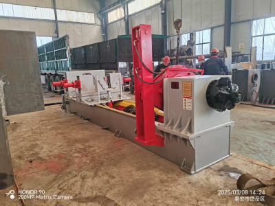
Horizontal Column Jack Disassembly Machine
Industry-Leading Torque – 300,000 N·m boost cylinder tackles even the most stubborn threaded connections.
Self-Locking Jaw Design – Eliminates hydraulic clamping complexity for faster, safer operation.
Triple Control Options – Choose between manual valves, button control, or remote operation.
Mine-Safe Construction – Emulsion fluid compatibility and explosion-proof electricals meet mining standards.
Giant Cylinder Capacity – Processes 50–500 mm diameter cylinders with 2.1m stroke adjustment.
WLCG500 Horizontal Column & Jack Disassembly Machine
The WLCG500 is a specialized disassembly/assembly machine designed for hydraulic cylinders used in coal mining support systems. Upgraded from earlier prototypes, it efficiently handles threaded-end hydraulic cylinders of various models, ensuring safe and precise maintenance.

Key Features & Structure
Versatile Compatibility – Dismantles and assembles large threaded hydraulic columns & jacks of all standard models.
Torque-Controlled Assembly – Ensures precise threaded fastening with preset torque.
Heavy-Duty Threaded Component Handling – Processes large threaded connections reliably.
Self-Locking Mechanism – Replaces traditional hydraulic clamping for simpler, more secure operation.
Mine-Grade Hydraulics – Uses emulsion fluid; pump station is separate from the host machine.
Standardized Components – Employs universal mining hydraulic parts for easy maintenance.
Safety Protections – Electrical controls include overload, short-circuit, and pressure-loss safeguards.
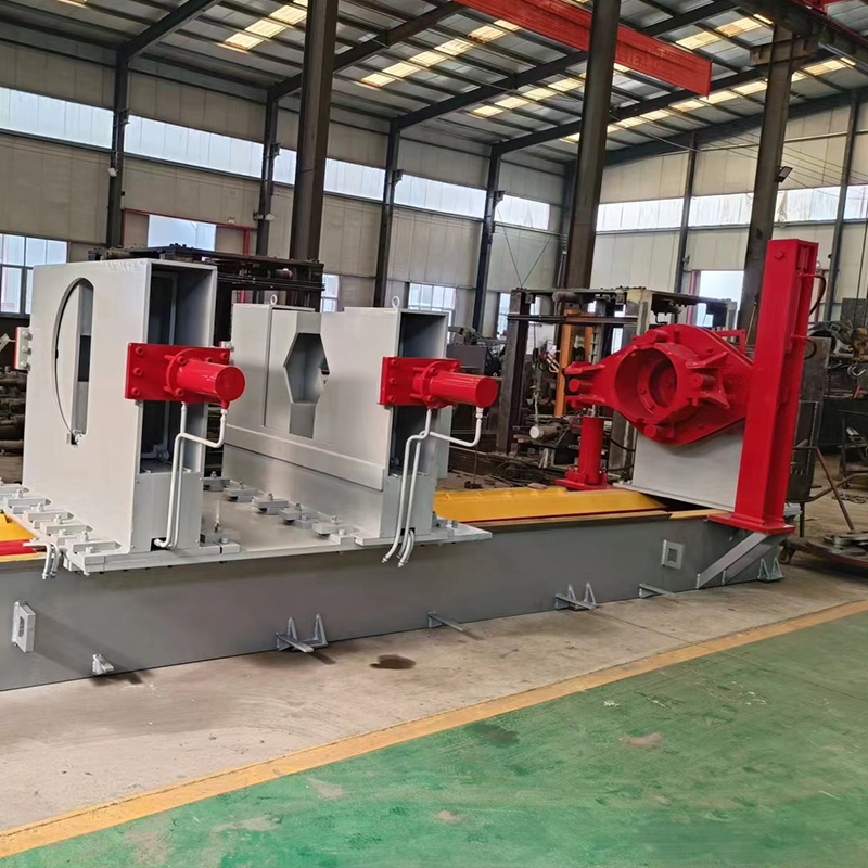
Main Components:
Frame
Clamping slide unit
Connection drum
Chuck
Hydraulic motor drive
Hydraulic control system
Electrical control system
Technical Specifications
| Parameter | Specification |
|---|---|
| Hydraulic Motor Power | 18.5 KW (4-Pole) |
| Disassembly/Assembly Torque | 30,000 N·m |
| Hydraulic Motor Flow Rate | 56 L/min |
| Pump Station Pressure | 31.5 MPa |
| Motor Working Pressure | 25 MPa |
| Boost Cylinder Torque | 300,000 N·m |
| Clamping Cylinder Max Thrust | 265 KN |
| Max Pulling Force | 180 KN |
| Compatible Cylinder Diameter | 50–500 mm |
| Translation Cylinder Stroke | 2,100 mm |
| Clamping Mechanism | V-Toothed Dual Jaw Plates |
| Operation Modes | Manual Valve / Button Control / Remote |
| Dimensions (L×W×H) | 7,000 × 2,400 × 1,700 mm |
Product Configuration
| Component | Model No. | Qty | Remarks |
|---|---|---|---|
| Motor | 18.5KW | 1 | |
| Hydraulic Motor | HZKY-01-001 | 1 | |
| Hydraulic Pump | HZKY-01-002 | 1 | |
| Control Valve | HZKY-01-003 | 8 sets | |
| Force Cylinder | HZKY-01-004 | 2 | |
| Clamping Cylinder | HZKY-01-005 | 2 | |
| Auxiliary Cylinder | HZKY-01-006 | 1 | |
| High-Pressure Hoses | - | 34 |
Operating Instructions
1. Pre-Operation Preparation
(1) Installation & Leveling
After delivery, lift and place the machine on a level foundation.
Adjust the guide rails horizontally using shims under the base.
Position the hydraulic power unit stably near the control panel.
Fill the tank with N46 anti-wear hydraulic oil up to 3/4 of the sight glass.
Connect 380V power supply with proper grounding.
(2) Power-On Test
Start the pump motor and check rotation direction (clockwise when viewed from the fan end).
Run the pump briefly several times to ensure smooth operation before continuous 10-minute no-load test.
(3) System Bleeding & Lubrication
Operate the clamping cylinder valve 3–5 times to purge air.
Cycle the push/pull cylinder 3–5 times for air removal.
Rotate the hydraulic motor clockwise/counterclockwise to lubricate ratchet mechanisms.
Apply grease to machine guide rails.
(4) Setup for Disassembly
Select the appropriate clamping plate based on cylinder size.
Install matching guide sleeve adapter (custom-made per cylinder type).
Adjust V-block height and clamping cylinder position to align with cylinder notches (prevents rotation).
Move the sliding table forward to engage the adapter with the disassembly chuck.
Start the thread-loosening rotation to remove the guide sleeve.
(5) Piston Removal
Hoist the cylinder and eject the piston using pneumatic/hydraulic pressure.
2. Disassembly Procedure & Guidelines
Pre-Cleaning: Thoroughly wash the cylinder exterior to remove coal dust, oil sludge, etc.
Pre-Installation Check: Confirm guide sleeve specifications and prepare corresponding adapters.
Example: 400mm Double-Extension Cylinder Disassembly
Lift the cleaned cylinder onto the machine and center it using the clamping cylinder.
Fine-tune alignment via the front centering mechanism to match the chuck’s axis.
Attach the adapter, advance the worktable, and interlock it with the chuck.
Start the motor—16MPa pressure typically suffices for sleeve removal.
For rusted/seized threads, activate the ratchet mechanism for higher torque.
Disassembly Methods:
Method A:
Remove middle cylinder sleeve → outer sleeve → hoist cylinder.
Extract the outer barrel using a puller machine.
Open the bottom valve and eject the piston.
Method B:
Remove outer sleeve first → extract middle cylinder.
Re-clamp the middle cylinder and disassemble its sleeve.
Use a puller for the piston/sleeve.
Method C: Default to Method A; switch to Method B if the middle cylinder rotates due to excessive sleeve tightness.
⚠ Critical Notes:
Surface Protection: Use rubber pads to prevent damage to precision parts.
Pressure Control: Gradually increase system pressure—never exceed 20MPa for the motor (rated torque) or 16MPa for the ratchet (120kN force).
Thread Care: Avoid sudden high-pressure rotation to prevent thread/structure damage.