
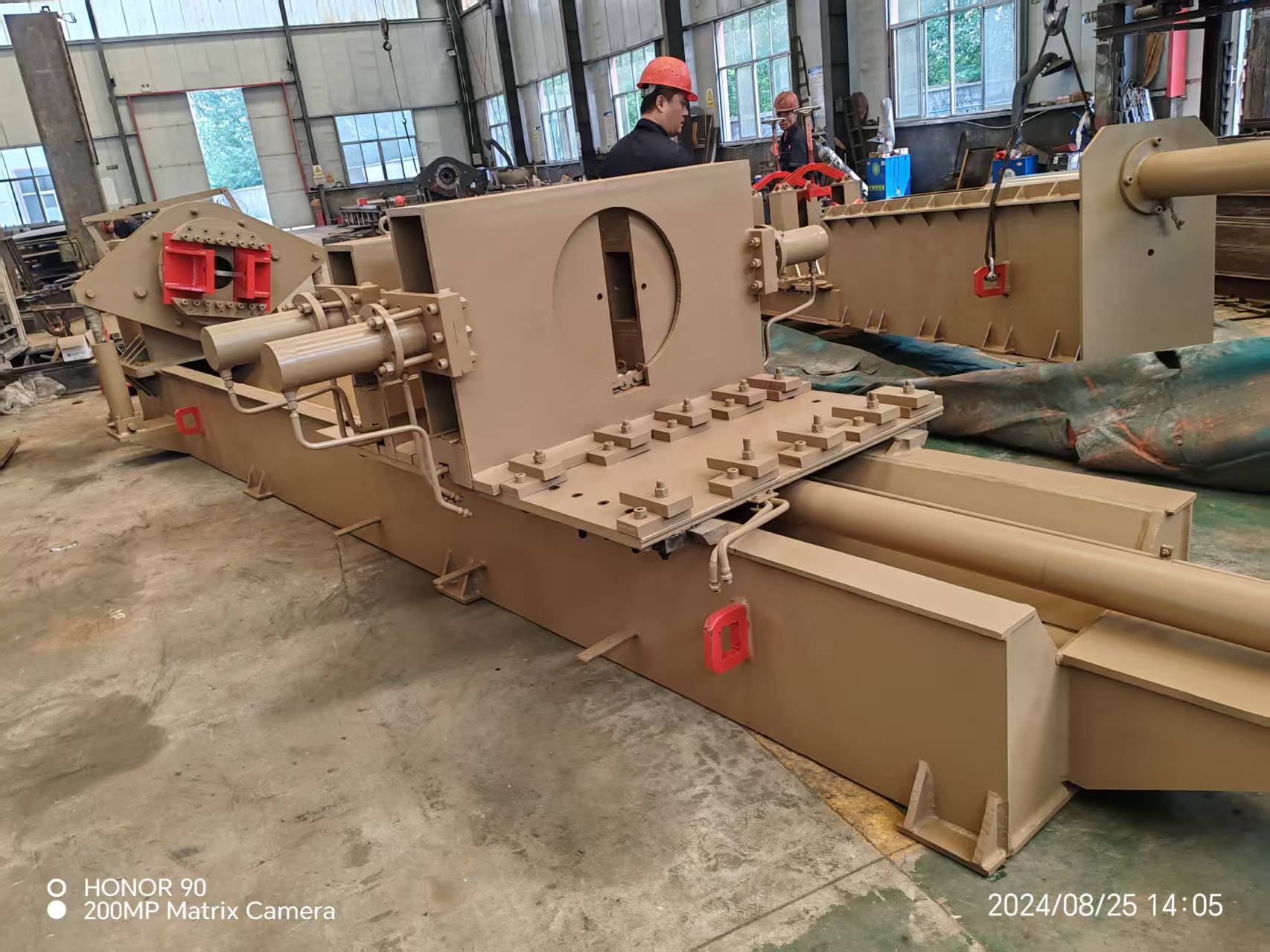
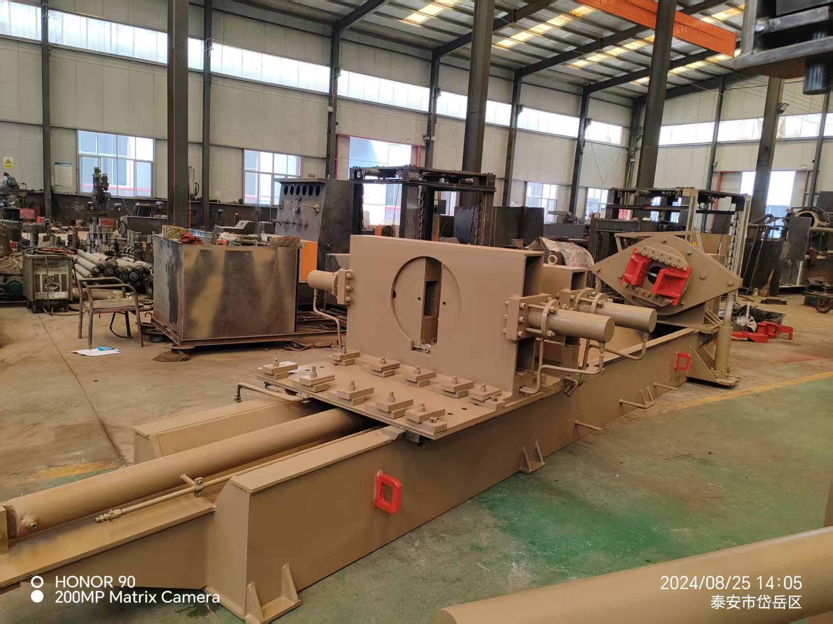
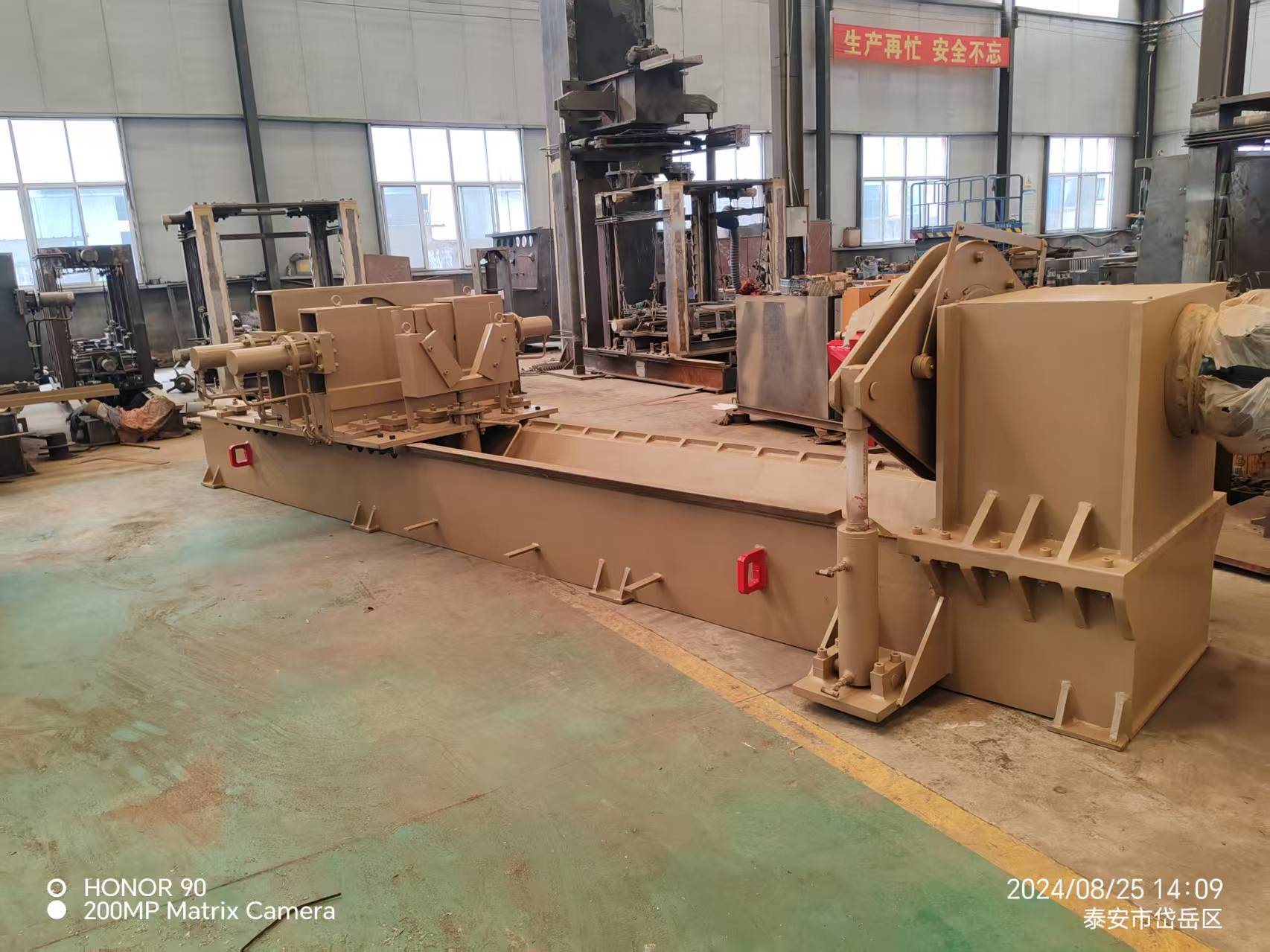
Benchtop Horizontal Hydraulic Actuator Disassembler
1. The gear wants to be leveled in the course of set up (error ≤0.2mm/m), fill N46 hydraulic oil to 3/4 level, and join 380V electricity provide and floor wire (resistance ≤4Ω).
2. When starting, first jog the oil pump 3-5 instances to verify the direction, run it besides load for 10 minutes, and display the noise (≤75dB), strain (±0.5MPa) and oil temperature (35-45℃).
3. During the pre-inspection, function every actuator 3-5 instances in full stroke, lubricate the ratchet mechanism and information rail (use NLGI 2# grease).
4. Select matching tooling (card tolerance ±0.1mm), alter the coaxiality (≤φ0.05mm), and loosen the thread after the information sleeve is engaged with the card die.
5. After disassembly, carry the cylinder body, use ≤20MPa strain to push out the plunger, and hold the straightness ≤0.1mm/m.
(Note: Operate in accordance to GB/T 3766 standard, key steps have to be demonstrated with the aid of two people, and the inclined iron wishes to be grouted after adjustment)
1. During the installation and commissioning phase, the equipment needs to be hoisted horizontally, and the machine tool guide rails should be adjusted to an error of ≤0.2mm/m using an inclined iron. After the main machine is leveled, the hydraulic station is positioned on the operating side, and the oil tank is filled with N46 anti-wear hydraulic oil to the 3/4 scale of the level gauge. At the same time, the electrical system is connected to a 380V three-phase power supply and the grounding resistance is ≤4Ω to complete the basic installation work.
2. When the hydraulic system is started, the oil pump motor should be activated 3-5 times to confirm that the fan end is clockwise, and then the system is run at no load for 10 minutes for system running-in. During this period, the pump group noise should be monitored to be ≤75dB, the pressure gauge fluctuation range is ±0.5MPa, and the oil temperature should reach the normal operating temperature range of 35-45℃ within 10 minutes.
3. The functional pre-inspection process requires the clamping cylinder and the push-pull cylinder to be operated in sequence to complete 3-5 full-stroke reciprocating movements to remove air. At the same time, the ratchet mechanism is lubricated by the hydraulic motor in forward and reverse rotation, and NLGI 2# lithium-based grease is added to the guide rail surface to ensure that all moving parts are fully lubricated.

4. During the tooling preparation and centering stage, a special card with a tolerance of ±0.1mm and a guide sleeve card corresponding to the cylinder diameter grouping should be selected according to the model of the oil cylinder to be disassembled. The coaxiality of the V-block center height and the clamping seat should be adjusted to ≤φ0.05mm. The guide sleeve and the card are precisely engaged by moving the slide table and then the thread loosening procedure is started.
5. After the core disassembly operation is completed, the cylinder body is transferred to the auxiliary station using a lifting device, and the piston is ejected according to the process requirements using a pneumatic/hydraulic ejection device with a pressure of ≤20MPa. The cylinder body straightness must be maintained at ≤0.1mm/m throughout the process to ensure the disassembly quality.
(Note: This operating procedure strictly follows the requirements of GB/T 3766 General Technical Standard for Hydraulic Systems. Key operating steps must be confirmed by two people. The amount of oil to be filled at each lubrication point must be determined in accordance with the equipment lubrication chart. After the inclined iron is adjusted, secondary grouting should be performed to ensure the stability of the equipment.)
Technical parameters:
Hydraulic Drive Motor | 18.5KW -4 stage |
Motor Disassembly Torque | 30000N.m |
Total Flow of Hydraulic Motor | 56L/min |
Pumping Station Pressure | 31.5Mpa |
Motor Working Pressure | 25Mpa |
Afterburner Torque | 300000N.m |
Maximum Thrust of The Clamping Cylinder | 265KN |
Maximum Pulling Force | 180KN |
Disassemble The Bore | 50-500 |
Translational Cylinder Stroke | 2100mm |
Secondary Cylinder Clamping | V-shaped tooth plate clamping |
How it Works | Control valve/button electric control/remote control |
Dimensions | 7000×2400×1700mm |
Product configuration:
Name | Model | Quantity |
Motor | 18.5KW | 1 unit |
Hydraulic Motor | HZKY-01-001 | 1 unit |
Oil Pump | HZKY-01-002 | 1 unit |
Control Valves | HZKY-01-003 | 8 groups |
Afterburner Cylinders | HZKY-01-004 | 2 pcs |
Tighten Up Left and Right | HZKY-01-005 | 2 pcs |
Auxiliary Cylinders | HZKY-01-006 | 1 pc |
High-pressure Hose | 34 articles |


