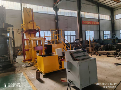
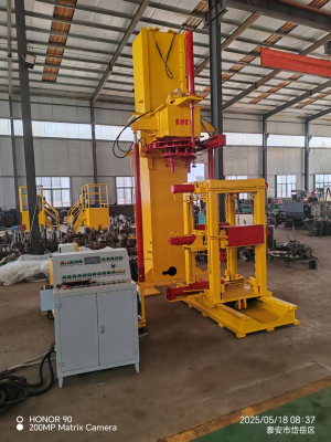
Column-type Cylinder Maintenance Bench
1. Preheat the equipment: Run the motor barring load for 10 minutes
2. Install the fixture:Select the corresponding fixture in accordance to the cylinder type
3. Fix the cylinder body:Install the cylinder barrel and begin the anti-sway device
4. Install the components:Insert the information sleeve,Lift the piston rod and make certain coaxiality
5. Pressing operation:Hydraulically press the piston rod after centering
6. Tighten the nut:Install the nut and anti-rotation tooling,Tighten the nut with the hydraulic motor
Column-type Cylinder Maintenance Bench Standard operating procedures:
1. Equipment preheating:Start the drive motor and keep it running at no load for more than 10 minutes to ensure that the hydraulic system reaches normal working condition.2. Fixture preparation:Install the corresponding positioning fixture assembly on the mobile workbench according to the specifications of the hydraulic cylinder to be assembled.

3. Cylinder body fixation:Accurately install the hydraulic cylinder body in the positioning fixture and enable the hydraulic support stabilization device to prevent axial deviation during assembly.
4. Component pre-installation
(1) Install the guide sleeve into the cylinder
(2) Use lifting equipment to lift the piston rod to the top of the cylinder
(3) Ensure that the piston rod and the cylinder are coaxially aligned
5. Pressing operation:Operate the reversing valve to control the movement and alignment of the workbench, and press the piston rod into the cylinder through the hydraulic pressing mechanism.
6. Thread tightening
(1) Install the end cover nut and special anti-rotation fixture
(2) Adjust the workbench so that the center of the cylinder body is aligned with the chuck
(3) Lower the hydraulic drive unit so that the claws engage the anti-rotation fixture
(4) Operate the hydraulic motor to complete the final tightening of the nut
7. Finishing
(1) Reset the hydraulic drive unit
(2) Release the fixture
(3) Use lifting equipment to remove the finished hydraulic cylinder
Note: This assembly operation must be performed by professional operators, and the system pressure and assembly alignment must be continuously monitored during the operation.
Technical Parameters:
| Dismantling column specifications | Cylinder diameter ≤500mm |
| Applicable cylinder length | ≤2500mm; |
| Motor dismantling torque | 30000N.m |
| Addition cylinder torque | 300000N.m |
| Motor power | 18.5kW |
| Flow rate | 56L/min |
| System pressure | 25Mpa |
| External dimensions (L×W×H) | 5×2.35×5.2m (underground part 1.7m) |
| Feeding trolley forward and backward travel distance | 1600mm |
| Dismantling cylinder stroke | 1200-2200mm |
| Clamping cylinder stroke | 200mm |
| Clamping diameter range | ≤600mm |
| Base lifting | 800mm |
| Base | Automatic clamping |
| Operation method | Manual direction change operation |
| Weight | 14.5T |
Main Configurations:
| Name | Model | Number |
| Motor | 18.5KW | 1 unit |
| Hydraulic Motor | HZYZ7 | 1 unit |
| Oil Pump | 40MCY14-1B | 1 unit |
| Manipulator Valve | ZS1- L20E-80TYW | 11 sets |
| Acceleration Cylinder | ¢125 Stroke 250 mm | 2 units |
| Lift Motor Cylinder | ¢100 Stroke 2.1m | 2 units |
| Feeding Trolley Cylinder | ¢100 Stroke 1.6m | 1 unit |
| Lifting Trolley Cylinder | ¢100 Stroke 600mm | 1 unit |
| Right and Left Holding Cylinder | ¢80 Stroke 250 mm | 2 units |
| Right and Left Tightening | ¢100 Stroke 250mm | 2 units |
| Backstop Cylinder | ¢63 Stroke 60mm | 1 unit |
| High pressure hose | 64 bars |
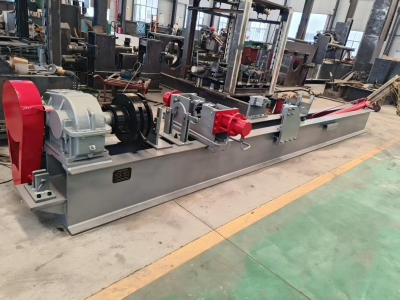
Real view of the factory: